
60V-2A DC-DC Module Converter (template)
Highlighted Feature
High efficiency monolithic synchronous step-down DC/DC converter utilizing a constant frequency, average current mode control architecture. Capable of delivering up to 1.5A continuous load with excellent line and load regulation. The device operates from an input voltage range of 7.5V to 60 V and provides an adjustable output voltage from 1.0V to 40V.
Features:
- Wide 7.5V to 60 V Operating input Range with
- maximum 100V transiens
- Peak Output Current: 2A
- 350μA Quiescent Current
- Adjustable Output Voltages
- Output Voltage Accuracy :±2%
- Frequency :350kHz
- Burst Mode Operation at Light Load
- Cycle-by-Cycle Over Current Protection
- Output Short Circuit Protection with Hiccup
- Internal Soft Start
Block Diagram

PCB Overview

Pin Out Table
| Pin 1 | Vin | 5-60V |
| Pin 2 | GND | 0V |
| Pin 3 | GND | 0V |
| Pin 4 | Vout | 1-40V |

Test Results
To test the efficiency, four multimeters are used; two are set up as voltmeters to measure the input and
output voltages, and two are set up as ampmeters to measure the input and output currents.
The measurements are done at a room temperature of 22.5ºC
Efficiency curve ( draw by excel)

Efficency table at 18V input
| V_in (V) | I_in (A) | V_out (V) | I_out (A) | η (efficency) |
| 17.77 | 0.725 | 11.99 | 0.997 | |
| 17.8 | 0.646 | 12 | 0.899 | 0.935516 |
| 17.82 | 0.55 | 12.02 | 0.7995 | 0.943191 |
| 17.85 | 0.477 | 12.03 | 0.699 | 0.947382 |
| 17.87 | 0.404 | 12.03 | 0.6 | 0.950832 |
| 17.89 | 0.337 | 12.03 | 0.5 | 0.954707 |
| 17.91 | 0.268 | 12.03 | 0.4 | 0.958073 |
| 17.93 | 0.201 | 12.1 | 0.301 | 0.958937 |
| 17.97 | 0.397 | 12.16 | 0.201 | 0.934149 |
Efficency table at 24V input
| V_in (V) | I_in (A) | V_out (V) | I_out (A) | η (efficency) |
| 7.77 | 0.697 | 5.072 | 0.997 | 0.933728 |
| 7.8 | 0.623 | 5.073 | 0.899 | 0.935516 |
| 7.82 | 0.55 | 5.074 | 0.7995 | 0.943191 |
| 7.85 | 0.477 | 5.075 | 0.699 | 0.947382 |
| 7.87 | 0.404 | 5.076 | 0.6 | 0.950832 |
| 7.89 | 0.337 | 5.077 | 0.5 | 0.954707 |
| 7.91 | 0.268 | 5.0775 | 0.4 | 0.958073 |
| 7.93 | 0.201 | 5.078 | 0.301 | 0.958937 |
| 7.95 | 0.1345 | 5.079 | 0.201 | 0.954739 |
Efficency table at 15V input
|
V_in (V)
|
I_in (A) | V_out (V) | I_out (A) | η (efficency) |
| 15.77 | 0.697 | 5.072 | 0.997 | 0.933728 |
| 15.8 | 0.623 | 5.073 | 0.899 | 0.935516 |
| 15.82 | 0.55 | 5.074 | 0.7995 | 0.943191 |
| 15.85 | 0.477 | 5.075 | 0.699 | 0.947382 |
| 15.87 | 0.404 | 5.076 | 0.6 | 0.950832 |
| 15.89 | 0.337 | 5.077 | 0.5 | 0.954707 |
| 15.91 | 0.268 | 5.0775 | 0.4 | 0.958073 |
| 15.93 | 0.201 | 5.078 | 0.301 | 0.958937 |
| 15.95 | 0.1345 | 5.079 | 0.201 | 0.954739 |
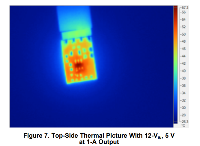
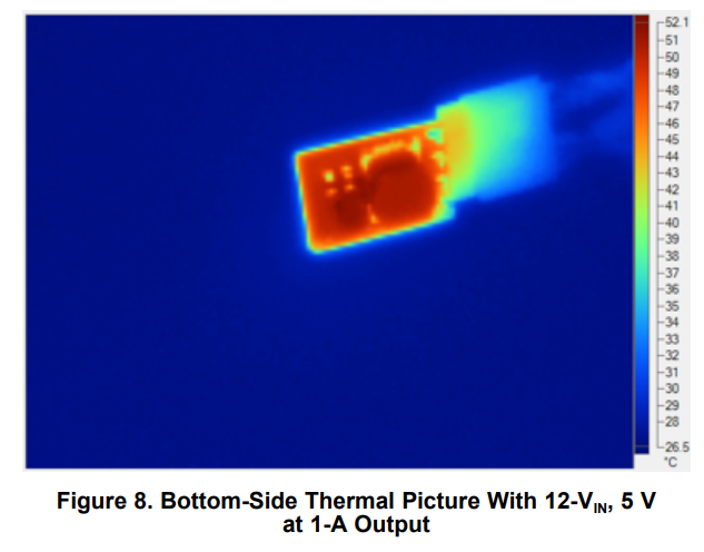
Thermal
The thermal pictures in below was taken at a room temperature of 26°C, with a 48-V input, 12V at 1-A output without airflow.
|
|
|
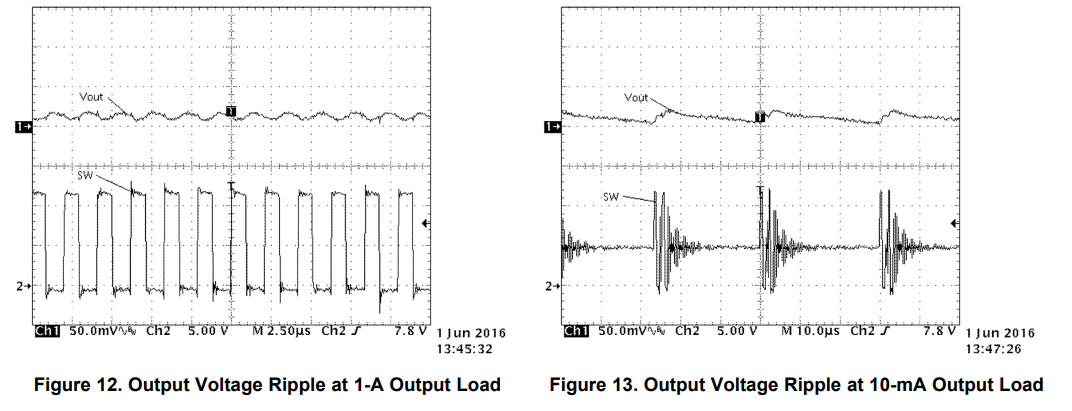
Output Voltage Ripple
How to measure ripple current with oscilloscope probe properly? read this document

Transient Response
The transient response is below ±200 mV for load steps between 10 mA and 1 A, which were the design
requirements (±5%).
Measurements were done at 22.5°C room temperature with 48-V input voltage. The upper curve (1) is the
output voltage with oscilloscope in AC-coupling mode with 100 mV/div. The lower curve (2) is the output
current with the current probe 100 mV/A with 200 mV/div. The load step is applied with a 250-mA/μs slew
rate.

Start-up and Shutdown
For the start-up and the shutdown behavior, 48 V is applied at the input with a 1-A load at the output.
The EN setting resistors (R2 and R5) are not populated, and the Enable pin is controlled with a 5-V signal.
Measurements were done at 22.5ºC room temperature. The upper curve (1) is the output voltage with
oscilloscope in DC-coupling mode with 2 V/div. The lower curve (2) is the Enable signal with 5 V/div.

Overcurrent and Short-Circuit Test
The overcurrent protection was tested by having a transient load from 1- to 3-A output current while the
board is supplied with 12 V. The short-circuit protection was tested by shorting the output pin to ground.


Standby and No-Load Currents
The no-load current was measured with an ammeter at 22.5°C room temperature with a 12-V input
voltage, with the enable setting resistors populated and no load attached at the output. The
no-load current was measured at 76 μA
Reference document: 5V 1A Low EMI 94% Efficiency DC/DC Module in Dual Layer TO-220 Design Guide (Rev. A)