FTR: 2.2uH 3A inductor
FUNCTIONAL TEST REPORT
DC-DC CONVERTER MODULE
Description: DC-DC CONVERTER MODULE TPS562201DDCR with 2.2uH 3A Inductor (SP26040439)
| Product Code | HW Version | 01 | ||
| Tested By | Date |
1. Required Equipment
-
DC Power Supply: Variable voltage with current limiting.
-
Electronic Load: Supporting CC (Constant Current) and CV (Constant Voltage) modes.
-
Oscilloscope: Minimum 100MHz bandwidth.
-
Digital Multimeter (DMM): High precision (4.5 digit preferred).
-
Thermal Measurement: IR Thermometer or Thermal Camera.
2. Test Set Up:
| Input (VDC) |
4V-12-24V ( increase step by step) | (according IC specs) |
| Output voltage(V) |
4V |
Test applied based on required voltage |
| Output current (A) | 0A -> 1.5A | (according IC specs) |
*Nominal value: 24V
3. Test Procedures
Step 1: Visual Inspection & Continuity Check
| Ref | Test Item | Acceptance Criteria | Result (P/F) | Notes |
| 1.1 | Visual Assembly | No missing components, no cold solder joints. | ||
| 1.2 | Input Impedance | Resistance between Input + and GND > 100kOhm | ||
| 1.3 | Output Impedance | Resistance between Vour+ and GND > 10kOhm |
Step 2: Basic Functional Test (No Load & Light Load)
| Ref | Test Condition | Parameters | Measured Value | Evaluation(P/F) | Note |
| 2.1 | Nominal Vin, No Load | Output Voltage(V) | |||
| 2.2 | Nominal Vin, No Load | Quiescent Input Current (mA) | |||
| 2.3 | Vin Min to Max range | Line Regulation (%) | How to test |
Step 3: Load Regulation & Efficiency Test
Set Vin to nominal value.
| Load (%) | Output Current (Iout) | Output Voltage (Vout) | Ripple (Vpk−pk) | Efficiency (%) |
| 10% | ||||
| 50% | ||||
| 100% |
Step 4: Dynamic Performance (Oscilloscope)Oscilloscope picture capture)
4.1 Ripple & Noise
Description: Check for high-frequency switching noise over range of input voltage
|
% Load |
10% Load |
50% Load |
75% |
100% |
Note |
|
Vin: 5V |
20mV | 25mV | 40mV |
30mV... |
|
|
Vin 12V |
|
|
|
|
|
|
Vin 24V |
|
|
|
|
|
| Ref | Test Item | Waveform Description | Measured (Pk-Pk) | |
| 4.1 | Ripple & Noise | Check for high-frequency switching noise. | Pick the highest value | |
| 4.2 | Soft-start / Startup | Smooth ramp-up, no significant overshoot. | ||
| 4.3 | Transient Response | Load step 25% |
Step 5: Protection Mechanisms
| Ref | Protection Type | Test Method | Module Behavior | Evaluation (Passs/Fail) |
| 5.1 | Over-Current (OCP) | Increase load to >120% of rated. | Shutdown or Foldback | |
| 5.2 | Short-Circuit (SCP) | Short the output terminals. | Hiccup or Shutdown | |
| 5.3 | Over-Temp (OTP) | High load + restricted airflow. | Thermal shutdown |
3. Thermal Analysis (After 30 min at Full Load)
-
Component Designator Temperature Note IC Controller IC1 Inductor L1 Capacitor C1 Capacitor C2.. PCB Inductor Temperature:...........$^\circ$C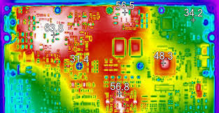
MOSFET/Diode Temp:............$^\circ$C
PowerThermal ICImage: Temperature: ........... $^\circ$C

4. Final Conclusion
$\square$ PASSED: Module meets all technical specifications.
$\square$ FAILED: Reasons: .............................................................................................................
Technician Signature
(Sign and print name)